Demo FishinoHomeAuto
What is FishinoHomeAuto ?
FishinoHomeAuto is a simple domotic application for Fishino boards.
 It creates a simple web server over which you can control some board's digital outputs and read both analog and digital inputs.
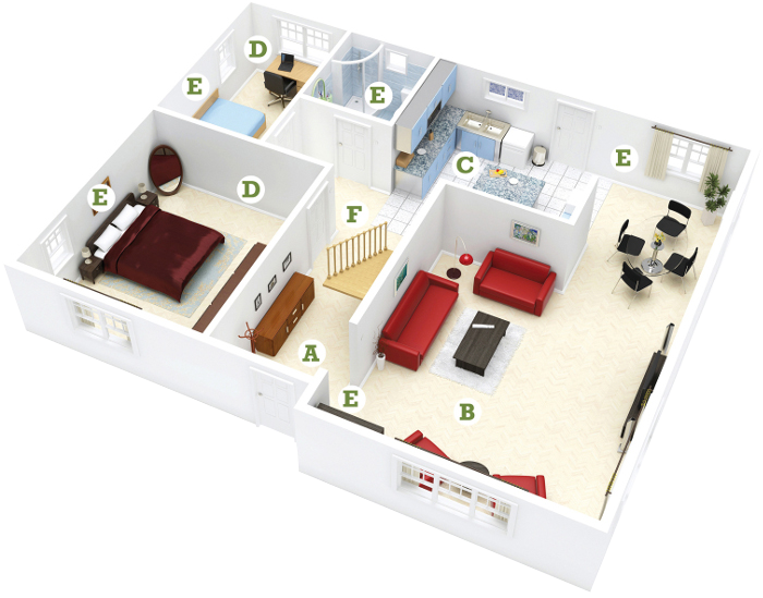
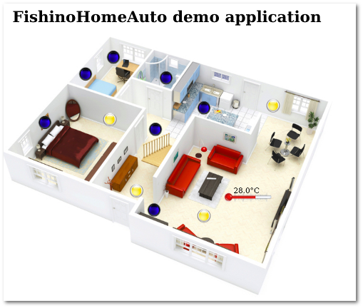
In this example we've created a web page with a picture of a flat with some interactive lights and a thermometer which displays one room's temperature.
Demo setup

You need a microSD card on which you shall put demo files.
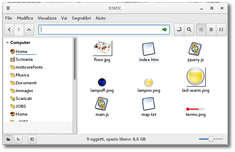
You can gather the example inside Fishino's library, folder examples/FishinoHomeAuto. The files for microSD card are all located in STATIC subfolder and must be copied in SD root folder; DO NOT copy the whole STATIC folder, just the single files. You shall get the content as shown in image here at left.
By now we don't change anything, we can see the flat's picture, the lamps (both on and off), the thermometer and some other files.
Sketch upload
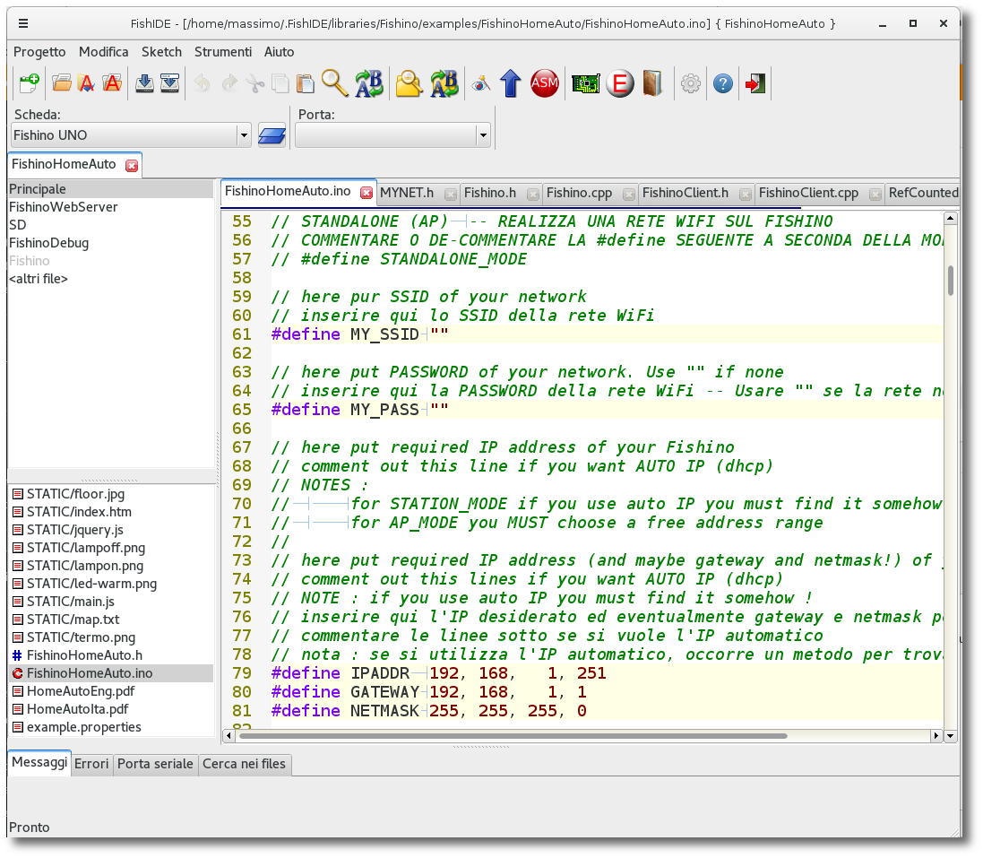
Let's open the FishinoHomeAuto.ino sketch inside IDE, choosing it among Fishino library's examples; we're using our FishIDE application, but you can use Arduino IDE as usual. 
#define STANDALONE_MODE#define MY_SSID "sweethome"
#define MY_PASS "1234"#define IPADDR 192, 168, 1, 10
#define GATEWAY 192, 168, 1, 1
#define NETMASK 255, 255, 255, 0Let's insert our microSD card in Fishino's slot and connect usb cable to PC, then open serial monitor and look ati it!
If all is ok, we shall see some info about the WiFi connection and the enabled appliances :
Resetting Fishino...OK
Connecting AP...OK
Waiting for IP.........OK
IP Address :192.168.1.251
Setting up SD card...
Found 12 appliances
l1:0:2
l2:0:3
l3:0:5
l4:0:6
l5:0:8
l6:0:9
l7:0:15
l8:0:16
l9:0:17
l10:0:18
l11:0:19
t1:3:0
Init done
Web server starting...
Ready to accept HTTP requests...Monitor's log shows us that :
- We're connected to our access point with IP address 192.168.1.251
- 12 appliances were found in our domotic house
- First 11 appliances, named from L1 to L11 are connected to digital outputs (:0) at ports 2, 3, 5, 6, 8, 9, 15, 16, 17, 18 and 19
- Latest appliance, named T1, is an analogic input (:3) connected to Fishino's A0 analog port
- Initialization was successful (Init Done)
- System is ready for remote connections (Web server starting...Ready to accept HTTP requests...)
Keeping serial monitor opened we fire our browser and point it to our IP address; on serial monitor we shall see a log with downloaded files:
Browser view
The browser will shoud our flat's picture, with the lamps initially off and the thermometer which shows a random temperature, as we've not connected a real sensor on analog input;clicking on lamps we can see them turn on and off and, at the same time, Fishino's digital outputs will change state accordingly. Connecting some LEDs on them we could see output's states:
File: INDEX.HTM
Read file INDEX.HTM
File: JQUERY.JS
Read file JQUERY.JS
File: MAIN.JS
Read file MAIN.JS
File: FLOOR.JPG
Read file FLOOR.JPG
File: MAP.TXT
Read file MAP.TXT
File: FAVICON.ICO
File: LAMPOFF.PNG
Read file LAMPOFF.PNG
File: TERMO.PNG
Read file TERMO.PNGTOGGLED APPLIANCE lx
(Where x is appliance's number).
TOGGLED APPLIANCE l1
TOGGLED APPLIANCE l4
TOGGLED APPLIANCE l9The application can be customized with few files; index.htm file contains the html code with flat picture's link, map.txt file which maps Fishino's I/O wth the appliances and their position over flat's pictureand some image files containing the images on the page (floor.jpg, lampon.png, lampoff.png, termo.png).
Let's examine the files in detail.
Map.txt file
At first we look at map.txt file, which is a simple text file containing JSON data :
{
"l1"  : {"kind":"do", "io" :  "2", "imageoff" : "lampoff.png", "imageon" : "lampon.png", "x" :  93, "y" : 367 },
"l2"  : {"kind":"do", "io" :  "3", "imageoff" : "lampoff.png", "imageon" : "lampon.png", "x" : 230, "y" : 374 },
"l3"  : {"kind":"do", "io" :  "5", "imageoff" : "lampoff.png", "imageon" : "lampon.png", "x" : 179, "y" : 469 },
"l4"  : {"kind":"do", "io" :  "6", "imageoff" : "lampoff.png", "imageon" : "lampon.png", "x" : 237, "y" : 504 },
"l5"  : {"kind":"do", "io" :  "8", "imageoff" : "lampoff.png", "imageon" : "lampon.png", "x" : 286, "y" : 224 },
"l6"  : {"kind":"do", "io" :  "9", "imageoff" : "lampoff.png", "imageon" : "lampon.png", "x" : 326, "y" : 353 },
"l7"  : {"kind":"do", "io" : "15", "imageoff" : "lampoff.png", "imageon" : "lampon.png", "x" : 348, "y" : 461 },
"l8"  : {"kind":"do", "io" : "16", "imageoff" : "lampoff.png", "imageon" : "lampon.png", "x" : 323, "y" : 183 },
"l9"  : {"kind":"do", "io" : "17", "imageoff" : "lampoff.png", "imageon" : "lampon.png", "x" : 428, "y" : 171 },
"l10" : {"kind":"do", "io" : "18", "imageoff" : "lampoff.png", "imageon" : "lampon.png", "x" : 428, "y" : 398 },
"l11" : {"kind":"do", "io" : "19", "imageoff" : "lampoff.png", "imageon" : "lampon.png", "x" : 573, "y" : 403 },
"t1"  : {"kind":"ai", "io" : "0", "image" : "termo.png", "x" : 520, "y" : 211, "scale" : 0.1, "delta" : -5, "prec" : 1, "textpref" : "", "textsuff" : "°C", "textx": 20, "texty" : 15 }
}
As you can see there are 2 parenthesis which enclose the whole block, and a series of text lines which describe the various appliances. Let's see a line relative to a lamp:
"l1" : {"kind":"do", "io" : "2", "imageoff" : "lampoff.png", "imageon" : "lampon.png", "x" : 93, "y" : 367 },The line starts with appliance's name ("l1"), followed by a semicolon (:) and a list of elements enclosed with parenthesis and which ends with a comma (,). The format is mandatory; evenn a small error, like a missing comma or a wrong character will make the whole system useless.
The elements between parenthesis are of kind key:value, where key is a name enclosed in quotation marks and the value can be a string, also quoted, or a number. All the appliances starts with appliance kind (kind) and the mapped 'I/O (io):
"kind":"do", "io" : "2", .....The meanings are straightforwad : "do" means "Digital Output"; for the thermometer we'll have "ai" which means "Analog Input". On example line we have a digital output connected to I/O 2 in Fishino board.
By now on javascript code we just support digital I/O (both input and output) and analog input; it would be possible to enhance it with an analog output adding a slider to the webpage.
Following values depends on appliance kind; for digital I/O we have 2 images, one which represents the LOW state and the other for HIGH state. In our example we've got a couple of lamps, one ON and the other OFF :
"imageoff" : "lampoff.png", "imageon" : "lampon.png", ...We see here the "lampoff.png" and "lampon.png" pictures. Last values are the position of the appliances on flat's picture, starting from lower left corner, in this case the point at 93;367. The position is fixed on appliance's center, to make it easy its positioning. In this case, the reference point is center of lamp's circle.
For analogic inputs, so our thermometer, we have :
"t1" : {"kind":"ai", "io" : "0", "image" : "termo.png", "x" : 520, "y" : 211, "scale" : 0.1, "delta" : -5, "prec" : 1, "textpref" : "", "textsuff" : "°C", "textx": 20, "texty" : 15 }So just one image ("image"), in this case the file "termo.png", followed by position over flat's picture (520, 211) and 2 conversion factors which are needed to convert the integer value read from Fishino's analog ports, which lies between 0 and 1023, in a floating value that represents the temperature. Used formula is :
temp = val · scale + deltaWhere 'temp' is displayed temperature, 'val' is the value returned by digitalRead and 'delta' is an additional shifting factor. Changing 'scale' and 'delta' values we can adapt our system on every analog sensor available. To understand how to calculate the values let's look at following example; imagine that we have a sensor which returns following values :
 220   for a temperature of -10 degrees
1100   for a temperature of 50 gradi
Let's calculate the 'scale' factor first :
scale = (50 - (-10)) / (1100 - 220) = 0.0681818And then the 'delta' value :
delta = temp - val · scale = 50 - 1100 · 0.06818 = -25All that works only if sensor is LINEAR over the whole temperature range; an NTC, for example, is NOT linear on a wide range, so we should modify our code with a better interpolation function, adding more constants on map file and patching our javascript code..
We find then a couple of strings which will be displayed before and after the numeric value ('textpref' e 'textsuff'); in our case we want to show the word "°C" after the number and nothing before.
Last but not least, we have another couple of coordinates which are used to position the value text over the appliance image; setting both to 0 will put the text over the image's center, which would not be too nice. In our case we shift it by 20 and 15 pixels to have a better display.
The index.htm file
This file is just a simple HTML file which has just the few needed parths to have our flat's picture displayed, the loading of our 2 javascript files a couple of embedded CSS styles to optimize element's positioning :
<html>
	<head>
		<meta charset="UTF-8">
		<meta name="viewport" content="width=device-width; initial-scale=1.0; maximum-scale=1.0; user-scalable=0;" />
		<meta name="HandheldFriendly" content="True" />

		<script type="text/javascript" src="jquery.js"></script>
		<script type="text/javascript" src="main.js"></script>

		<title>Fishino Home Automation Demo</title>
	</head>
	<body>
		<h1><center>FishinoHomeAuto demo application</center></h1>
		<style>
			#container {
				position:relative;
				display:table;
				margin: 0 auto;
			}
			.itemcontainer {
				position:absolute;
				display:block;
			}
			.imtip {
				position:relative;
			}
			.texttip {
				position:absolute;
			}
		</style>
		<div id="container" align="center" border-color="red" border-width=2>
			<img src="floor.jpg"/>
		</div>
	</body>
</html>
You can change almost all in this file, from the background picture going on. With some work it's possible to build a multipage home automation controller.